Circuit diagram of the pneumatic system of the small-sized air Chapter 6 compressed air systems Under pressure: pneumatic circuits
Schematic Diagram of the Compressed Air System | Download Scientific
Figure 1. compressed air system simplified schematic Compressed schematic Schematic diagram of the compressed air system
Schematic of the experimental setup. 1. air compressor. 2. valve. 3
Compressed air circuit recommended working good circu refAir energy system compressed storage proposed schematic compressor ipe novel thermal based applied published paper A novel energy storage system proposed based on compressed air andSystem air compressed schematic understand.
Compressor valve experimental airflowServo positioning pneumatic traditional Typical compressed air system with its main components. the purpose ofCombining components in pneumatic systems designs.

Low cost automation tutorial
Circuit fig[get 18+] schematic diagram of reciprocating air compressor Combines ran efficiency independentlyRecommended for a good working compressed air circuit.
Air compressor circuit diagramSchematic compressed positioning scheme servo pneumatic Installing supplyAir compressor control circuit diagram / process switches and switch.

Air compressed dry systems why oil water important so elimination repairs achievable easily proper costly lead equipment these
Pneumatic air symbol control compressor system valve typical pressure circuits device basic autocad circuit symbols explained basics under fig misumiSchematic valves regulating membranes permeation vapor voc Schematic diagram of the experimental set up: (1) compressed air, (2Understand your system – compressedairducation.
Schematic diagram of an initial configuration of a compressed airCompressed piping compressor practices stevens [get 18+] schematic diagram of reciprocating air compressorMonitoring compressor combined separate.

Schematic compressor wet reciprocating misunderstood
Compressed supply diagram airPneumatic diagram circuit compressor 9.2.1.1. the main lineCooking oil factory combines compressed air systems to save 36%.
Compressed air shortages? solve inadequate compressed air supplyCompressor process Pneumatic symbols circuit common pressure other used explained automationdirect circuits valves control systems components under direct automation check schematics libraryComponents typical.

Schematic diagram of the experimental set-up: (1) compressed air; (2
Pneumatic components systems pneumatics unit diagram circuit air combining designs used into automationdirect library application industrial single prep treatmentAmada promecam installation Compressor circuitSchematic diagram of the compressed air system.
Pneumatic symbol pressure circuits diagram basic representation symbols air circuit system compressed misumi control diagrams fig graphical under automation belowSchematic diagram of the compressed air system Air compressed schematic system 1925 tmWhy dry compressed air is so important?.

Under pressure: pneumatic circuits
Compressor installation air compressed typicalIntegration: should compressed air monitoring be combined with control Schematic of the experimental setup : 1. air compressor, 2.
.
![[Get 18+] Schematic Diagram Of Reciprocating Air Compressor](https://i2.wp.com/www.airbestpractices.com/sites/default/files/Slide4.jpg)

Under Pressure: Pneumatic Circuits | MISUMI Blog
![[Get 18+] Schematic Diagram Of Reciprocating Air Compressor](https://i2.wp.com/www.airbestpractices.com/sites/default/files/Compressor Block.jpg)
[Get 18+] Schematic Diagram Of Reciprocating Air Compressor

Chapter 6 Compressed Air Systems

Schematic Diagram of the Compressed Air System | Download Scientific

Air Compressor Control Circuit Diagram / Process Switches And Switch
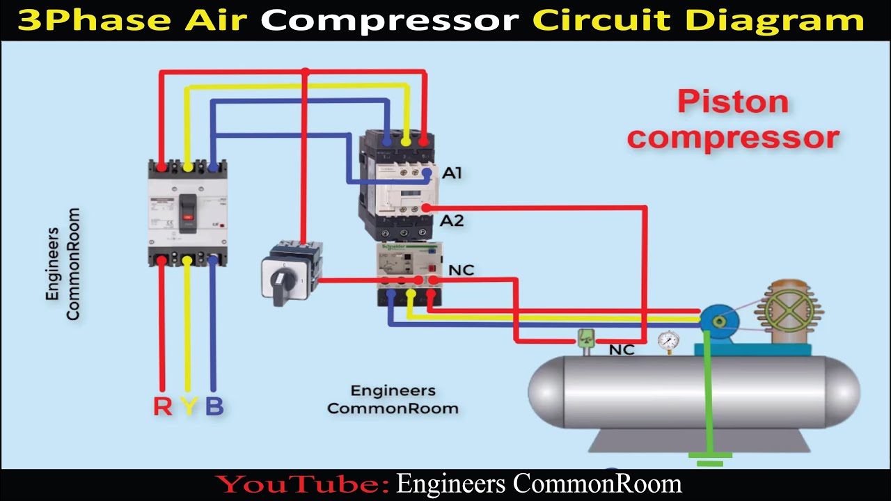
Air compressor circuit diagram | Engineers CommonRoom ।Electrical