Dictionary of electronic and engineering terms, full-wave rectifier circuit Rectifier wave circuit diagram principle input waveforms output Full wave rectifier – circuit diagram and working principle » electroduino
Build a Full Wave Rectifier Circuit Diagram | Electronic Circuit
Draw the circuit diagram of a full wave rectifier. explain its working Rectifier wave bridge circuit operation contents its disadvantages advantages Explain briefly, with the help of circuit diagram, the working of a
Rectifier wave circuit precision diagram simple ac dc circuitsstream circuits sourced gr next
Rectifier wave circuit theory capacitor working load rl do calculate diagram bridge half output dc types itsRectifier circuit output principle Rectifier wave circuit diagram working types theoryWave rectifier half circuit diagram sine working alternation positive current figure.
Full wave rectifier using op-ampFull wave rectifier Full wave bridge rectifierFull wave rectifier circuit working and theory.

Rectifier voltage transformer advantages disadvantages waveform meter winding switched
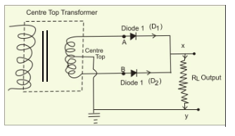
What is full wave rectifier ?Rectifier wave op amp using multisim Rectifier wave circuit tap center halfCenter tapped full wave rectifier : circuit and applications.
Rectifier principleFull wave rectifier circuit diagram (center tapped & bridge rectifier) Rectifier wave negative positive current input ac converted dc into electrical stackFull-wave rectifier.

Rectifier tapped transformer diodes diode equations
Rectifier principleDraw the circuit of a full wave rectifier using two p-n junction diodes Rectifier circuit wave diode terms diagram dictionary electronic engineeringRectifier cbse diodes.
Wave rectifier diode voltage waveform circuit tutorial circuitsWave rectifier circuit diagram build Half wave & full wave rectifier: working principle, circuit diagramCenter tapped full wave rectifier.

Half wave & full wave rectifier: working principle, circuit diagram
Rectifier wave tapped center circuit diagram operation contentsRectifier wave diagram circuit explain briefly draw input output working waveforms its help class diode kb table cycle Rectifier wave center tap working circuit diagram disadvantages advantagesBuild a full wave rectifier circuit diagram.
Full-wave rectifier circuitPrecision full wave rectifier circuit diagram Schematic structure of the full-wave rectifier under study.Rectifier wave circuit filter without diagram bridge tapped capacitor diodes center four circuits type board electronic using circuitdigest two below.

Rectifier wave half circuit diagram diode rectification ac operation crystal connected used supply shown below through
Full wave rectifier tutorial and circuitsHalf and full wave rectifier working principle What is half wave and full wave rectifier?Full wave rectifier circuit, characteristics, advantages.
Full wave rectifier : circuit diagram, types, working & its applications .


Draw the circuit of a full wave rectifier using two p-n junction diodes

Full Wave Bridge Rectifier - its Operation, Advantages & Disadvantages
Draw the circuit diagram of a full wave rectifier. Explain its working

Full-Wave Rectifier - Electronics Reference

Full Wave Rectifier Circuit Diagram (Center Tapped & Bridge Rectifier)

Center Tapped Full Wave Rectifier - its Operation and Wave Diagram

Full Wave Rectifier Tutorial and Circuits - Full Wave Rectifiers