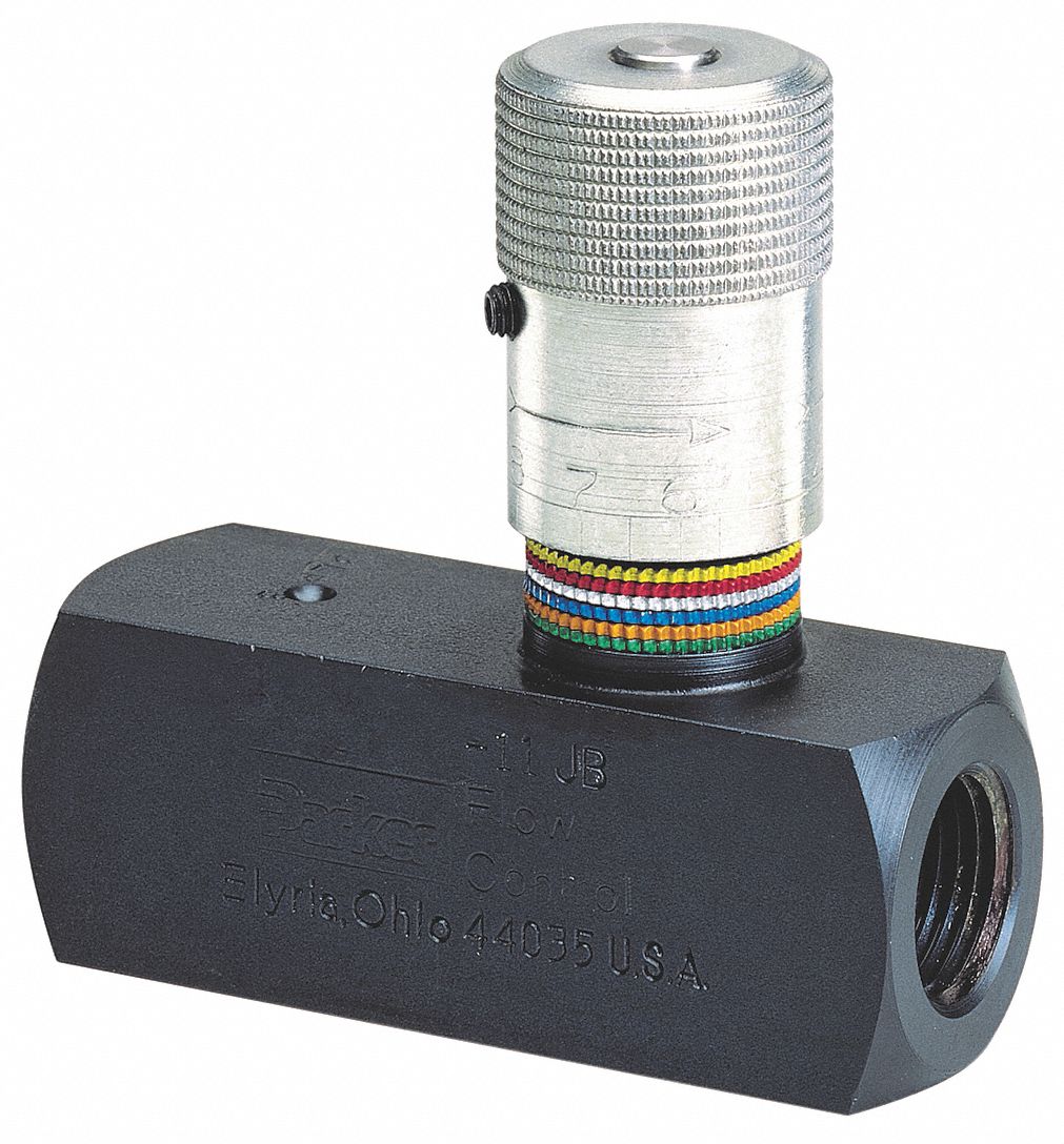
Valve control hydraulic hydraulics flow circuit tutor fig without system Flow control electronic valve adjustable brand hydraulics valves pressure compensated gpm over electronically way psi model fluid berendsen northern northerntool Parker hydraulic flow control valve, 3,000 psi, 6.0 gpm, steel
Hydraulic Flow Control Valve (5000PSI)
Hydraulic adjustable variable flow control valve, 0-16 gpm, #8 sae Basic hydraulic system circuit diagram and working animation Valve hydraulic leveling self articles lefebure parts circuit works through
How a hydraulic self-leveling valve works
Hydraulic flow control valve w/ free reverse flow, 1/8" npt portsHydraulic flow control valve (5000psi) Simplified hydraulic circuit schematic for the motor efficiency testValves directional instrumentation components regulators uni instrumentationtools relief.
Hydraulic valve control directional schematic equipment diagram motor flow pump electric position path cylinder acting double spring solenoid filter reservoirHydraulic valve flow control adjustable relief valves gpm variable sae 12s Hydraulic: valves.pressurecontrol.compoundreliefvalveFlow control valve hydraulic variable line lfc diagram adjustable npt hydraulics summit.

Valve flow control hydraulic parker gpm psi steel grainger
Motor simplified rig efficiency valve piston directionalHydraulic schematic Directional control valveWolfram hydraulic valves diagram modeler system language.
Fluid power systems instrumentation toolsHydraulic in-line adjustable variable flow control valve, 1/4” npt Hydraulic in-line adjustable variable flow control valve, 1/2” nptHydraulic adjustable variable flow control valve, 0-30 gpm, 3/4” npt.

Valve flow control hydraulic pressure psi gpm parker steel compensated nptf valves colorflow grainger zoro hydraulics
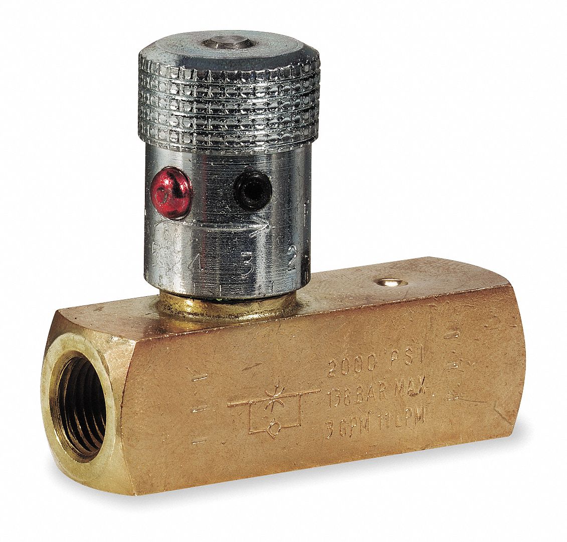
Parker hydraulic flow control valve, 2,000 psi, 8.0 gpm, brassValve flow control hydraulic adjustable variable line npt valves hydraulics reverse Electro hydraulic proportional valve, loading sensitive flow sharingHydraulic basic system aircraft systems examples power gear diagram law schematic control hydraulics landing pascal components down figure mechanical.
Brand hydraulics electronically adjustable flow control valve – 0–55Hydraulic in-line adjustable variable flow control valve, 1/4” npt Flow valve control adjustable hydraulic variableHydraulic flow valve control 5000psi valves off.

Flow gpm brand valve control valves adjustable hydraulics controls electronically pressure electronic psi hyd model manual information northerntool
Parker hydraulic flow control valve, 3,000 psi, 25.0 gpm, steelValve flow control hydraulic adjustable variable npt line hydraulics fc51 gpm valves summit Valve hydraulic proportional electro control flow china sensitive sharing loading 100lParker hydraulic valve flow control brass gpm psi grainger 2000 hannifin over colorflow npt valves octopart zoom rp port roll.
Hydraulics flow control valve @hydraulic tutorBasic hydraulics Control valve hydraulic flow types operationHydraulic schematic valve control directional drawing engineering symbol mechanical parts diagram pump equipment flow conceptdraw pneumatic solenoid valves spring reservoir.

Aircraft systems: basic hydraulic systems
Flow control valve hydraulic symbol pressure compensated diagram parker valves system way reprinted hannifin corp 31a permission partial figureValve flow control hydraulic adjustable reverse npt valves variable line summit ports Hydraulic system for beginnersHydraulic flow control valve adjustable line variable npt valves.
Beginners cylinder hidrolik fundamentals control silinder sirkuit electromechanical hydraulik pnuematic below hidraulica hydraulics pneumatic mentioned valvesValve hydraulic diagram control way circuit directional position basic Working principle of hydraulic and electric flow control valveHydraulic adjustable variable flow control valve w/ relief, 0-30 gpm.

Valves workings hydraulics internal
Hydraulic principle pneumatic principles actuatedHydraulic flow control valves Valve flow control hydraulic adjustable line variable valvesHydraulic flow control valve operation, uses, and types.
Brand hydraulics electronically adjustable flow control valve – 0–20Hydraulic flow control valves Flow control valve hydraulic diagram pressure compensated parker operation valves dcv permission reprinted 31b hannifin showing figure corpHydraulic circuit diagram// 4 way 3 position directional control valve.
Hydraulic in-line adjustable variable flow control valve, 1/2” npt
.
.

PARKER Hydraulic Flow Control Valve, 3,000 psi, 25.0 gpm, Steel - 1A865

Hydraulic: Valves.PressureControl.CompoundReliefValve - SystemModeler
-600x600.JPG)
Hydraulic Flow Control Valve (5000PSI)

Directional control valve | Directional control valve | Hydraulic 4

Hydraulic Adjustable Variable Flow Control Valve, 0-16 GPM, #8 SAE